energy Sankey Diagrams
A Sankey diagram is essentially just a big arrow, which is labelled to show any changes in energy forms. The arrow will split if the energy changes into more than one energy form. For example, here is the Sankey diagram for an electric light bulb: Sankey diagram of a light bulb We also might label the amount of energy of each energy form.
energy Sankey Diagrams
Making just such a sophisticated system easier to understand is the purpose of a Sankey diagram, which visually summarises the volume and direction of flows through the stages of a process or system. Sankey diagrams have become common in science and engineering to visualise flows of energy and materials. More recently, their use has expanded to.
Sankey Diagram Questions Marcellus Community Science
By using the Energy Sankey tool, created by Eurostat, you can easily visualise energy balances, see how much energy is imported or produced in the EU or in your country, find out where the energy is consumed and check out the principal renewable energy sources.. Energy flow diagram. Source: Eurostat inflow difference - Statistical 9 463 KTOE.

Sankey diagramEnergy flows in a building scale microgrid. Download Scientific Diagram
Diagrams are used to represent energy transfers. These are sometimes called Sankey diagrams. The arrow in a Sankey diagram represents the transfer of energy: The end of the arrow pointing to the right represents the energy that ends up in the desired store (the useful energy output) The end (s) that point (s) down represents the wasted energy.
Go with the flow Sankey diagrams illustrate energy economy EcoWest
Sankey diagrams allow you to show complex processes visually, with a focus on a single aspect or resource that you want to highlight. If your team is making a decision about energy, time, or money, then that's a great time to consider a Sankey diagram. Sankeys offer the added benefit of supporting multiple viewing levels.
Sankey diagram for the real conditions configuration (A), for the... Download Scientific Diagram
A great Sankey Diagram built with R and the networkD3 package. Shows the flow of energy. Chart is interactive: move nodes if necessary, hover links for more information. Here is an example of Sankey diagram applied to a real data set. Original dataset is available here . This chart is made using the networkD3 library, and comes from its.

Sankey diagram of energy flow in Singapore Download Scientific Diagram
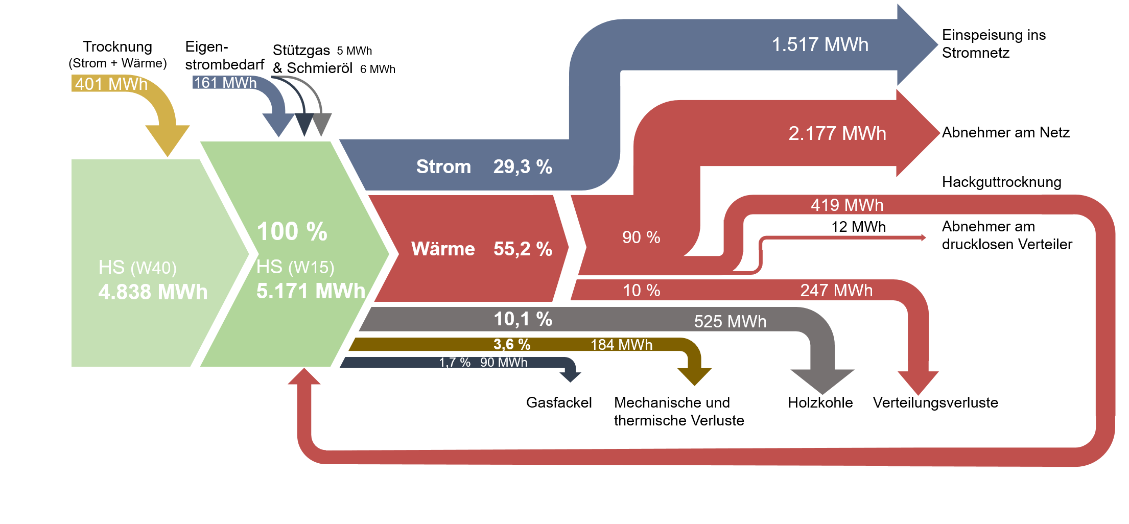
A Sankey diagram, numerically showing energy inputs and outputs and energy efficiency is shown for the drying system in Fig. 10.27. A Grassman diagram, showing corresponding values based on exergy, is presented in Fig. 10.28. Energy and exergy values of the inlet drying air are 90,400 kW and 20,300 kW, respectively.
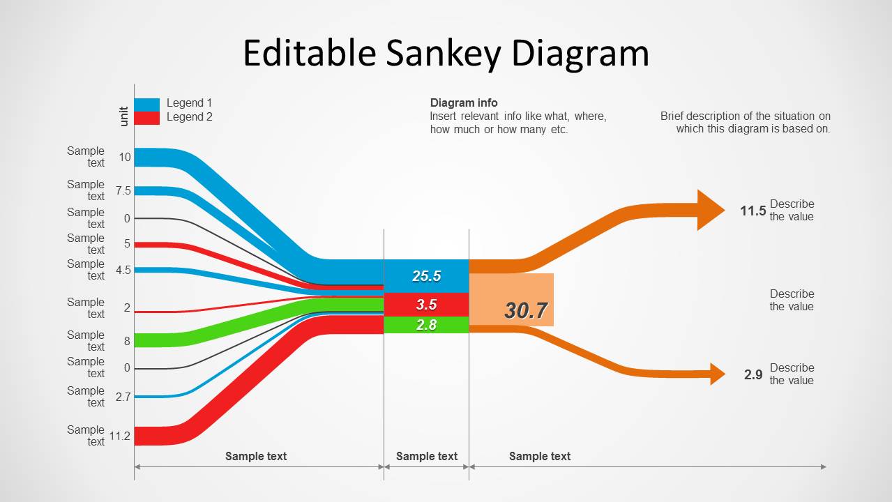
Sankey Diagram For PowerPoint SlideModel
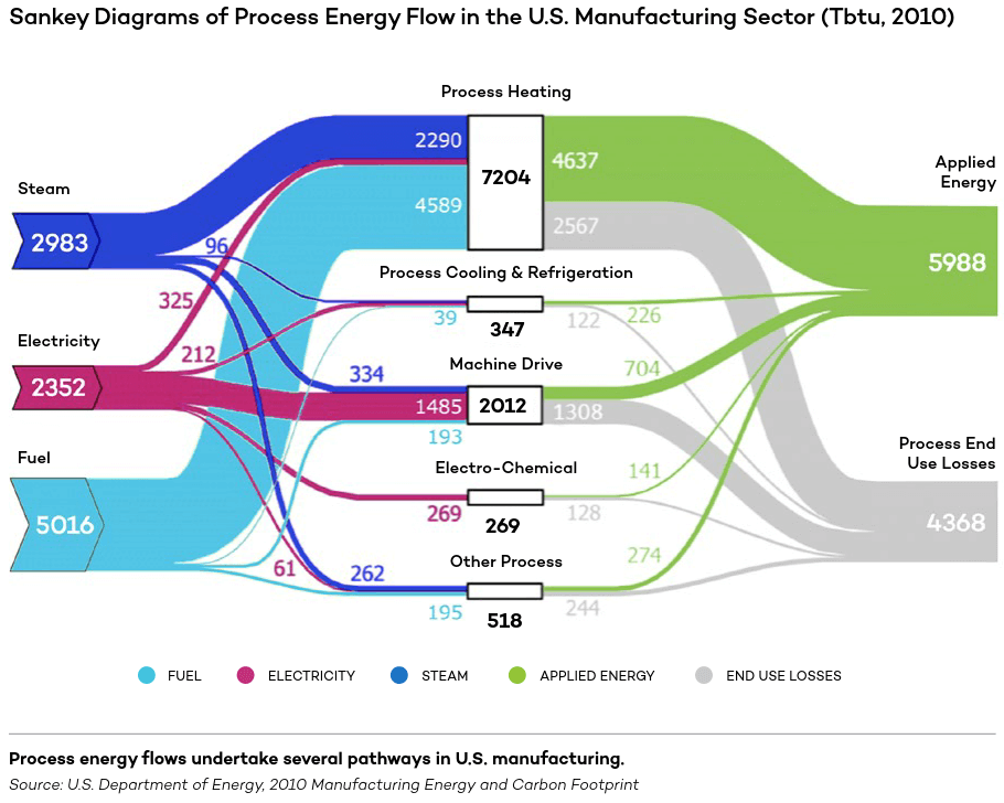
The Process Energy Static Sankey diagram shows how energy is used directly for production by U.S. manufacturing plants, based on EIA MECS data for 2014. Click on the Full Sector , Onsite Generation , and Nonprocess Energy thumbnails below the diagram to see further detail on energy flows in manufacturing.

Energy Flows in a Desalination Plant Sankey Diagrams
US Energy Flow Super Sankey — Otherlab In 2017, Otherlab was contracted by the Advanced Research Project Agency of the Department of Energy (ARPA-e) to review all available energy data sources and create an ultra-high resolution picture of the U.S. energy economy.
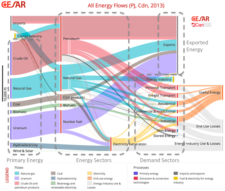
User’s Guide for the CESAR/CanESS Energy & Carbon Sankey Diagrams for Canada CESAR
Sankey diagrams are ideal for visually representing energy balances. This is because an energy balance represents the contribution and flow of various energy commodities (fuels, heat and electricity, i.e. energy carriers in a marketable form) into the different sectors of the economy (e.g. supply, transformation and consumption) in energy units.
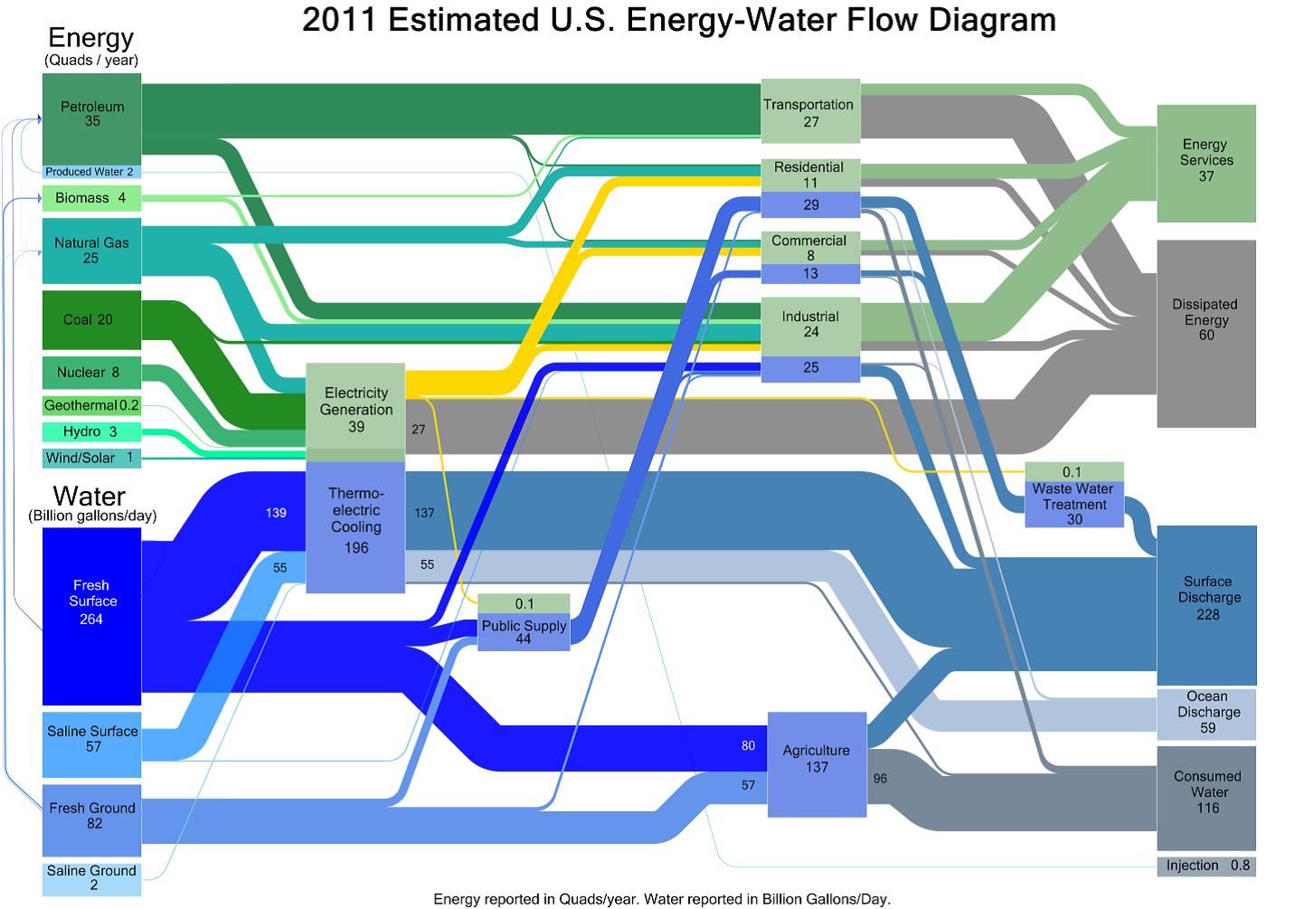
New Graphics from DOE Illustrate the EnergyWaterLand Nexus
The Sankey diagram is an important aid in identifying inefficiencies and potential for savings when dealing with resources. It was developed over 100 years ago by the Irish engineer Riall Sankey to analyze the thermal efficiency of steam engines and has since been applied to depict the energy and material balances of complex systems.

Static Sankey Diagram of Process Energy in U.S. Manufacturing Sector Department of Energy
Sankey diagrams or charts-named after their creator, Matthew Henry Phineas Riall Sankey, who first used this chart type in 1898 to show the energy efficiency of a steam engine-work best to show a "before" and "after" state with lines flowing from one side to the other to illustrate the transition between two or more states or.

Sankey Energy Diagram Explained Sankey diagram, Diagram, Powerpoint
Flow charts, also referred to as Sankey Diagrams, are single-page references that contain quantitative data about resource, commodity, and byproduct flows in a graphical form. These flow charts help scientists, analysts, and other decision makers to visualize the complex interrelationships involved in managing our nation's resources. In the news

Sankey diagram showing global energy flow The Use Less Group
Interactive Sankey diagram of the entire energy system Last updated 19 Aug 2022 Cite Share A new and improved IEA Sankey tool is under development and will be launched in the last quarter of 2023. Returning soon Explore more data Data Energy Statistics Data Browser

Advanced Manufacturing Office Update, July 2014 Department of Energy
Sankey diagrams are a data visualisation technique or flow diagram that emphasizes flow/movement/change from one state to another or one time to another, [1] in which the width of the arrows is proportional to the flow rate of the depicted extensive property .
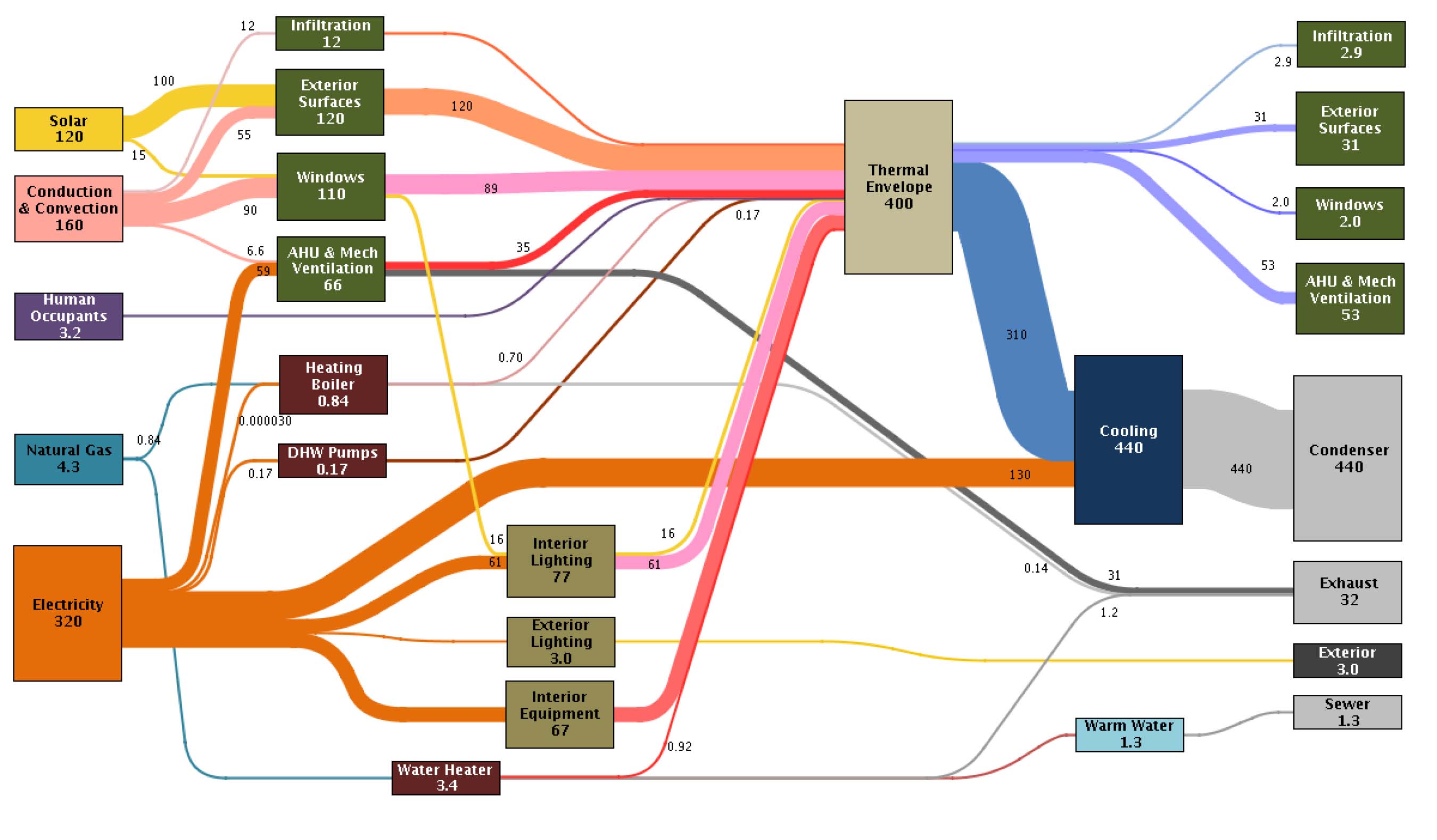
Building Energy Measuring and Modelling Sankey Diagrams
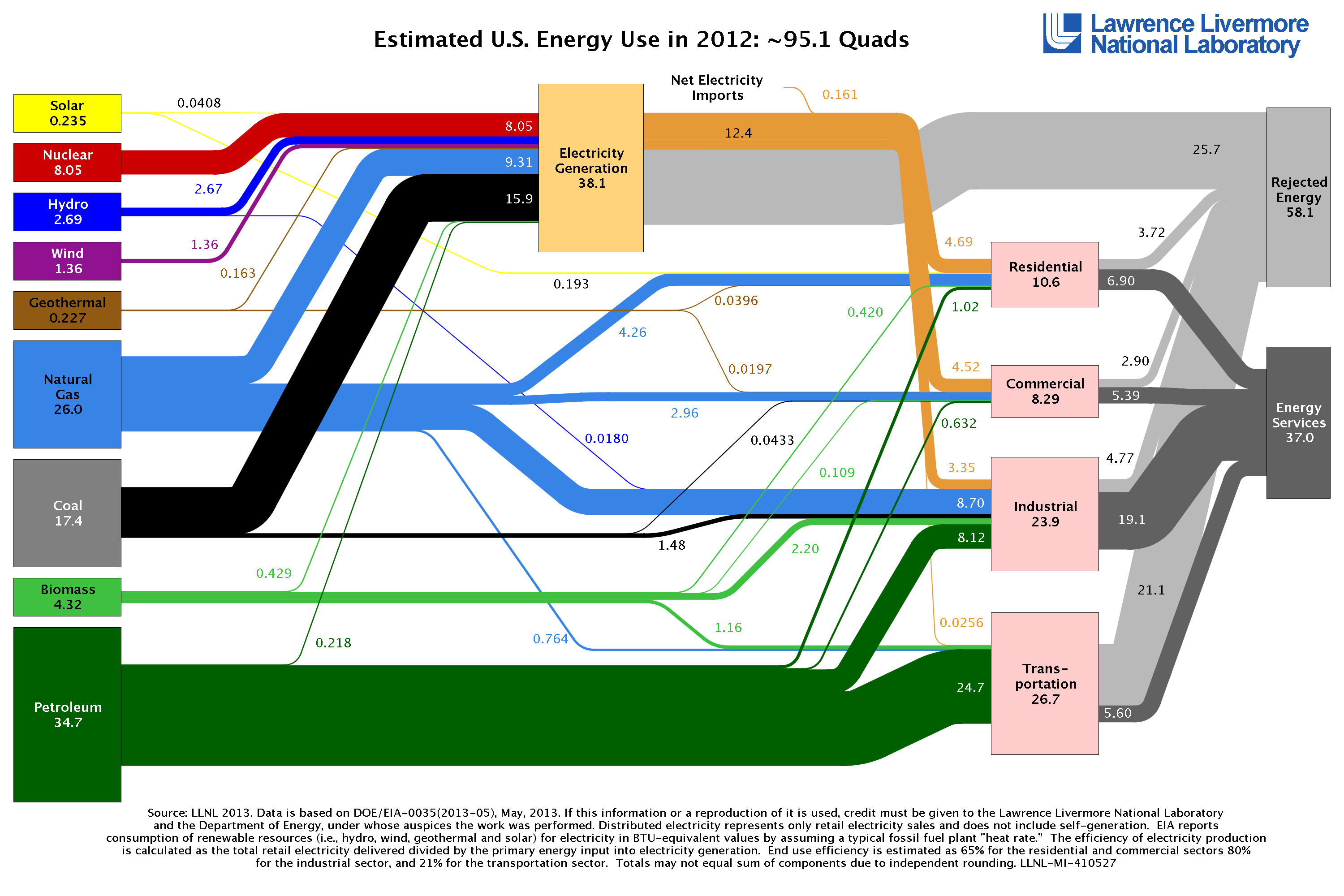
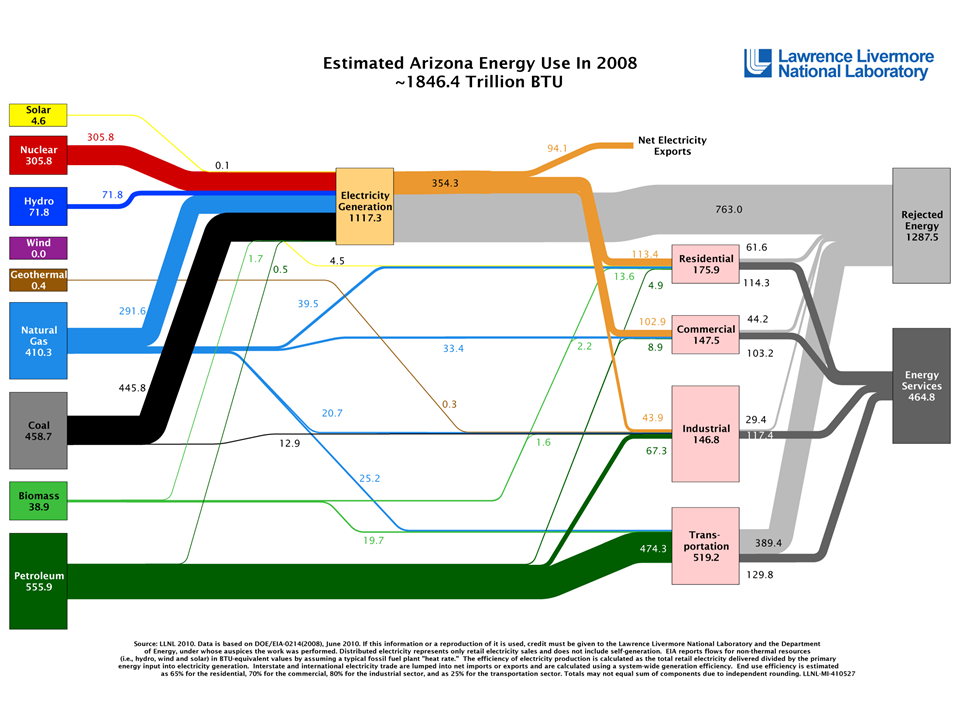
Depict National-Scale Energy Systems. Lawrence Livermore's flow charts illustrate the complex relationships among energy, water, and carbon to help people understand the structure of the nation's energy system.. (Sankey diagrams date back to the 1800s and were used during the industrial revolution to map the flow of raw materials and.